
That's nicely in tune.
JAPton blog
-
Rockburner

- Posts: 6033
- Joined: Sun Mar 15, 2020 11:06 am
- Location: Hiding in your blind spot
- Has thanked: 10959 times
- Been thanked: 3995 times

-
Rockburner
- Posts: 6033
- Joined: Sun Mar 15, 2020 11:06 am
- Location: Hiding in your blind spot
- Has thanked: 10959 times
- Been thanked: 3995 times
Re: The JAPton Rebuilders Manual!
Small update.
I haven't really made much progress, but things have happened.
I found the ONLY piece of JAP hardware at Beaulieu Autojumble: a head, complete with fitted valves! Snapped it up for £130 and kindly refused the same seller's offer of £475 for an AMAL Type 27 twin float-chamber dope-sucker!
I think the Head was made up for use, and then either only used very briefly, or put to one side as a "ready spare".
It holds water :

But I want to be sure that's it's fully-functional condition so I've started stripping it down to check valve-stem rattles etc:

It's pretty clean.

But there's always room for improvement... (that's the exhaust outlet)

The valves springs sit in these cups:

And you have mica washers that sit underneath the cups to adjust the valve-spring compression. LIttle bit of verdigris here...

I've also arranged to take the crank up to the JAP speedway guru in a few weeks to strip it down, check the bearings and rebuild it (it's beyond my equipment and capabilities to rebuild the crank!) I'll hopefully be able to take some photos of the process, if I'm allowed.
I've also just put in an order for a few bits..... around £600s worth..... (new main bearings, new big-end bearings, new cam-roller, etc etc).
every step is a step forward.... (even if they're not very often!)
I haven't really made much progress, but things have happened.
I found the ONLY piece of JAP hardware at Beaulieu Autojumble: a head, complete with fitted valves! Snapped it up for £130 and kindly refused the same seller's offer of £475 for an AMAL Type 27 twin float-chamber dope-sucker!
I think the Head was made up for use, and then either only used very briefly, or put to one side as a "ready spare".
It holds water :
But I want to be sure that's it's fully-functional condition so I've started stripping it down to check valve-stem rattles etc:
It's pretty clean.
But there's always room for improvement... (that's the exhaust outlet)
The valves springs sit in these cups:
And you have mica washers that sit underneath the cups to adjust the valve-spring compression. LIttle bit of verdigris here...
I've also arranged to take the crank up to the JAP speedway guru in a few weeks to strip it down, check the bearings and rebuild it (it's beyond my equipment and capabilities to rebuild the crank!) I'll hopefully be able to take some photos of the process, if I'm allowed.
I've also just put in an order for a few bits..... around £600s worth..... (new main bearings, new big-end bearings, new cam-roller, etc etc).
every step is a step forward.... (even if they're not very often!)
non quod, sed quomodo
-
Rockburner
- Posts: 6033
- Joined: Sun Mar 15, 2020 11:06 am
- Location: Hiding in your blind spot
- Has thanked: 10959 times
- Been thanked: 3995 times
Re: The JAPton Rebuilders Manual!
In the interests of keeping up to date.... I also did some work last night.
Finished stripping down the "new" head. It's tidy.

The valve stems aren't the same - the inlet especially looks to have been either cut short, or made that way to reduce interference on the flow of the charge?


About an hour or so later after a dubious application of Solvol and a toothbrush...


Bit nicer.
Polished up the back face of the valves too...


and then gave them a bit of a grind. I only used the "fine" grinding paste because they were sealing nicely before, and I just wanted to ensure the mating face was good after the polish. Obviously I'll test the seals again after reassembly.

Terrible photo of the excellent valve tool I inherited from my Dad.


That's a big hole....

I also took some measurements of the inlet manifolds on each head. I'd read something about the evolution of the engine recently (must dig it out again), and that last photo made me curious....
Yup - they're different.
Head 1 (current) is 28.5mm / 1 1/8" internal diameter
Head 2 (new) is 32mm / 1 1/4" internal diameter.
I "believe" I'm right in thinking that if I want to use Head 2 (it's in better nick, has better valve stems and would appear to be "less old"), then I'm going to have to look for a new carb. IIRC the inlet manifold needs to be a consistent diameter/cross-sectional area for as much as is possible - which would mean that the carb would need to be consistent with that too. The current carb is an AMAL Monobloc (389/229) which measures 1 1/8" across the "exit" hole (ie where the fuel/air mixture exits the carb). (Oddly, the AMAL website suggests (although they've taken off the details now) that that model Monoblox is a 1 5/32" which is ... err... 1 2.5/8" (I think...)). So... I'm a little confused about that .....
It does mean I have a reason to potentially get a better carb though.... According to this site (https://surreycycles.com/carburettors/a ... c-376-389/) there is no 1 1/4" Monobloc so I don't believe I can get the same carb and therefore have use of my now extensive collection of jets...) Something different then.... probably something like a Mk1 Concentric or something. I do have to say it's very tempting to look at some throaty Dellorto or something equally esoteric though.... might suit the "crazy ... like a fox" nature of the bike.
Finished stripping down the "new" head. It's tidy.
The valve stems aren't the same - the inlet especially looks to have been either cut short, or made that way to reduce interference on the flow of the charge?
About an hour or so later after a dubious application of Solvol and a toothbrush...
Bit nicer.
Polished up the back face of the valves too...
and then gave them a bit of a grind. I only used the "fine" grinding paste because they were sealing nicely before, and I just wanted to ensure the mating face was good after the polish. Obviously I'll test the seals again after reassembly.
Terrible photo of the excellent valve tool I inherited from my Dad.
That's a big hole....
I also took some measurements of the inlet manifolds on each head. I'd read something about the evolution of the engine recently (must dig it out again), and that last photo made me curious....
Yup - they're different.
Head 1 (current) is 28.5mm / 1 1/8" internal diameter
Head 2 (new) is 32mm / 1 1/4" internal diameter.
I "believe" I'm right in thinking that if I want to use Head 2 (it's in better nick, has better valve stems and would appear to be "less old"), then I'm going to have to look for a new carb. IIRC the inlet manifold needs to be a consistent diameter/cross-sectional area for as much as is possible - which would mean that the carb would need to be consistent with that too. The current carb is an AMAL Monobloc (389/229) which measures 1 1/8" across the "exit" hole (ie where the fuel/air mixture exits the carb). (Oddly, the AMAL website suggests (although they've taken off the details now) that that model Monoblox is a 1 5/32" which is ... err... 1 2.5/8" (I think...)). So... I'm a little confused about that .....
It does mean I have a reason to potentially get a better carb though.... According to this site (https://surreycycles.com/carburettors/a ... c-376-389/) there is no 1 1/4" Monobloc so I don't believe I can get the same carb and therefore have use of my now extensive collection of jets...) Something different then.... probably something like a Mk1 Concentric or something. I do have to say it's very tempting to look at some throaty Dellorto or something equally esoteric though.... might suit the "crazy ... like a fox" nature of the bike.
non quod, sed quomodo
-
cheb
- Posts: 5462
- Joined: Tue Mar 17, 2020 6:51 am
- Been thanked: 2727 times
Re: The JAPton Rebuilders Manual!
I was taught to use petrol or paraffin to check valve seats, it's runnier that water.
How about a flat slide carb? That'd irk the purists.
How about a flat slide carb? That'd irk the purists.
-
Rockburner
- Posts: 6033
- Joined: Sun Mar 15, 2020 11:06 am
- Location: Hiding in your blind spot
- Has thanked: 10959 times
- Been thanked: 3995 times
Re: The JAPton Rebuilders Manual!
Surely water molecules are smaller and thinner than anything carbon based?cheb wrote: Wed Jun 04, 2025 5:13 pm I was taught to use petrol or paraffin to check valve seats, it's runnier that water.
How about a flat slide carb? That'd irk the purists.
non quod, sed quomodo
-
Count Steer

- Posts: 15906
- Joined: Mon Jul 19, 2021 4:59 pm
- Has thanked: 8035 times
- Been thanked: 5694 times
Re: The JAPton Rebuilders Manual!
Probably more to do with surface tension/wetting than molecule size. It's ST that determines if stuff 'creeps' through gaps iirc.Rockburner wrote: Wed Jun 04, 2025 7:28 pmSurely water molecules are smaller and thinner than anything carbon based?cheb wrote: Wed Jun 04, 2025 5:13 pm I was taught to use petrol or paraffin to check valve seats, it's runnier that water.
How about a flat slide carb? That'd irk the purists.
The gaps are much bigger than molly kules.
The plural of 'anecdote' is not 'data'.
-
Rockburner
- Posts: 6033
- Joined: Sun Mar 15, 2020 11:06 am
- Location: Hiding in your blind spot
- Has thanked: 10959 times
- Been thanked: 3995 times
-
Rockburner
- Posts: 6033
- Joined: Sun Mar 15, 2020 11:06 am
- Location: Hiding in your blind spot
- Has thanked: 10959 times
- Been thanked: 3995 times
Re: The JAPton Rebuilders Manual!

The old head is slowly cleaning up. I resorted to violence last night (with the dental pick).
Old photo for comparison:


bzzzzzzzzzzzzzzzzzzzzzzzzzzzzzzzzzzzzzzzzzzzzzzzzzzzzzzzzzzzzzzzzzzzzzzzzzzzzzzzzzzzzzzzzzzzzzzzzzzzzzzzzzzzzzzzzzzzzzzzzzzzzzzz

They might not look it, but they're a lot cleaner!
Did the valves and springs in petrol, and the rest in paraffin (the only 2 solvents I had in).
Will get most of the rest of the components cleaned up as I start reassembly, once the crank is done. Off to Ipswich next weekend for that.
non quod, sed quomodo
-
Taipan

- Posts: 19325
- Joined: Sat Mar 14, 2020 1:48 pm
- Location: Essex Riviera!
- Has thanked: 20857 times
- Been thanked: 13672 times

-
Rockburner
- Posts: 6033
- Joined: Sun Mar 15, 2020 11:06 am
- Location: Hiding in your blind spot
- Has thanked: 10959 times
- Been thanked: 3995 times
-
Count Steer
- Posts: 15906
- Joined: Mon Jul 19, 2021 4:59 pm
- Has thanked: 8035 times
- Been thanked: 5694 times
Re: The JAPton Rebuilders Manual!
Have a Google.
Walnut shell makes a nice enviro-friendly abrasive but it's not too fierce.
I think there was a project to see what uses waste walnut shells could be put to some time ago. Walnut shell flour finds a way into many things (not culinary!).
The plural of 'anecdote' is not 'data'.
-
Rockburner
- Posts: 6033
- Joined: Sun Mar 15, 2020 11:06 am
- Location: Hiding in your blind spot
- Has thanked: 10959 times
- Been thanked: 3995 times
Re: The JAPton Rebuilders Manual!
Progress thus far:
First, the dinosaurs came, but they got all fat and sick and died and turned into oil, then came Mercedes Benzes....
ahem.
The visit up to the JAP guru in Ipswich went very well indeed. We got on very well and it was a fun morning of fettling.
I took up a few parts to get his opinion on their worthiness and discovered a few things.
Firstly - the 2nd head I bought is badly pocketed: the valves have been sunk into the head so far (by use and grinding in) that they're actually now "outside" the original hemisphere shape of the combustion chamber. I also found out the other day that the original head has had the valve-seats replaced (I think I knew this), so it's actually in better condition than Head 2 (despite Head 2 being cleaner... ).
In addition we dicovered that the exhaust valve for Head 1 is bent. That was a puzzler - because there's no evidence of it having hit anything within the chamber (the other valve, or the piston). It's why it wasn't sealing. Luckily he had a 2nd valve that slotted right in.
We also looked at the loose inlet guide, and he replaced it from his stock. I didn't know this... but the valve guides can just be hammered in and out! The original valve fits in the new guide perfectly, so Head 1 will be back in action once it's fully cleaned up and re-lapped in. I'll probably by some flap wheels for my Dremel and have a go at the carbon build ups in the exhaust manifold myself, and then as a final resort take it to a media blaster of some sort. (walnut or vapour probably).
We also examined the rocker box : This is the best pic I could get of the issue :

What I thought was wear caused by too much endplay in the rocker arms, is actually caused by the fact that the rocker arms are the wrong arms for the box! Well - not actually "wrong" - but they've not been fettled properly! The original forging patterns for the rocker arms make them too big for the rocker-box, and it's necessary to grind off a lot of the material. When he's doing race-engines apparantly he takes off quite a lot of the material on the rocker arms, including drilling lightening holes and a hole down the ball-end! (sounds painful!). So - I'm going to take off the material necessary from the rocker arms to ensure that there is clearance for the oil-gallery (shelf), and get that oil-shelf rebuilt up - that should ensure that the rocker-bearings get plenty of oil in the future. I'm hoping that I'll be able to do that to a reasonable quality using hand-tools... we'll see.
He also explained a good trick for checking the valve-spring weights, which I'll take photos of as I do it.
He checked the piston - it's fine (needs a clean), and the cam-shaft - which is a "standard", not a race item (which is fine), and also explained a few tricks for getting that aligned correctly should it need it. All stuff I'll be checking when I reassemble it.
Then we got onto the crank (and I remembered I had a camera.... )
Separating the big end shaft from the flywheel


Big end rollers - all looked ok

The big end cage is just ally - but it looked ok.

Inner faces:


At this point there was a slight bit of confusion due to the distinct lack of balancing holes having been drilled in the inner faces, until I remembered it's a 350 crank (not a 500). Obviously new cage and rollers were fitted.

Pressing the tapered big-end shaft back into the flywheel.

With some minor adjustments to get the outer diameter faces parallel :
(I now want a brass hammer!)

Things are much easier when you have the right kit....

More minor adjustments to the get the shafts aligned :

This was very much an iterative process: take a measurement, squeeze the wheels, take a measurement, squeeze again... etc. etc

The for the first few checks the nut wasn't even done up as tight as it could be ... just f-ing tight. After getting it pretty damned close, he did the nut up even tighter (using a 4-foot breaker bar and a lot of bodyweight....) then spent another half-hour getting it just right: toed IN 3/4 of a thousandth of an inch on one side, and about 1 thou on the other side. Apparently under heavy load the crank can toe "out" and pinch the con-rod, so he sets them up toed in slightly.
At the end of the session he declared that it was a "good set of wheels". Which I'm very happy about! They should now be good for quite a while, and with the use I'm expecting from the bike (pottering about locally annoying the purists) they should outlast me.
As we were tidying up and nattering (another half hour at least... ) he realised that I didn't have a mag-platform steady bracket: it should look like this :


And this is how it's mounted : to the underside of the mag-platform, and to the crankcases.


The problem this fixes is engine vibration cracking the mag-platform supporting structure. So, while I have no idea why the engine didn't have one, it looks like a good idea to have one fitted so I'll try to either source one (I really should have asked him about that - so I probably will), or make one up. It needs to be good strong steel. (or whatever that fancy bronze-looking one is).
I now have all the parts ready, but still a lot of cleaning to do, and a few other optimisation jobs (eg lapping in the timing cogs to their shafts, and even lapping in the head to the barrel!).
First, the dinosaurs came, but they got all fat and sick and died and turned into oil, then came Mercedes Benzes....
ahem.
The visit up to the JAP guru in Ipswich went very well indeed. We got on very well and it was a fun morning of fettling.
I took up a few parts to get his opinion on their worthiness and discovered a few things.
Firstly - the 2nd head I bought is badly pocketed: the valves have been sunk into the head so far (by use and grinding in) that they're actually now "outside" the original hemisphere shape of the combustion chamber. I also found out the other day that the original head has had the valve-seats replaced (I think I knew this), so it's actually in better condition than Head 2 (despite Head 2 being cleaner... ).
In addition we dicovered that the exhaust valve for Head 1 is bent. That was a puzzler - because there's no evidence of it having hit anything within the chamber (the other valve, or the piston). It's why it wasn't sealing. Luckily he had a 2nd valve that slotted right in.
We also looked at the loose inlet guide, and he replaced it from his stock. I didn't know this... but the valve guides can just be hammered in and out!
The original valve fits in the new guide perfectly, so Head 1 will be back in action once it's fully cleaned up and re-lapped in. I'll probably by some flap wheels for my Dremel and have a go at the carbon build ups in the exhaust manifold myself, and then as a final resort take it to a media blaster of some sort. (walnut or vapour probably).We also examined the rocker box : This is the best pic I could get of the issue :
What I thought was wear caused by too much endplay in the rocker arms, is actually caused by the fact that the rocker arms are the wrong arms for the box! Well - not actually "wrong" - but they've not been fettled properly! The original forging patterns for the rocker arms make them too big for the rocker-box, and it's necessary to grind off a lot of the material. When he's doing race-engines apparantly he takes off quite a lot of the material on the rocker arms, including drilling lightening holes and a hole down the ball-end! (sounds painful!). So - I'm going to take off the material necessary from the rocker arms to ensure that there is clearance for the oil-gallery (shelf), and get that oil-shelf rebuilt up - that should ensure that the rocker-bearings get plenty of oil in the future. I'm hoping that I'll be able to do that to a reasonable quality using hand-tools... we'll see.
He also explained a good trick for checking the valve-spring weights, which I'll take photos of as I do it.
He checked the piston - it's fine (needs a clean), and the cam-shaft - which is a "standard", not a race item (which is fine), and also explained a few tricks for getting that aligned correctly should it need it. All stuff I'll be checking when I reassemble it.
Then we got onto the crank (and I remembered I had a camera.... )
Separating the big end shaft from the flywheel
Big end rollers - all looked ok
The big end cage is just ally - but it looked ok.
Inner faces:
At this point there was a slight bit of confusion due to the distinct lack of balancing holes having been drilled in the inner faces, until I remembered it's a 350 crank (not a 500).
Obviously new cage and rollers were fitted.Pressing the tapered big-end shaft back into the flywheel.
With some minor adjustments to get the outer diameter faces parallel :
(I now want a brass hammer!)
Things are much easier when you have the right kit....
More minor adjustments to the get the shafts aligned :
This was very much an iterative process: take a measurement, squeeze the wheels, take a measurement, squeeze again... etc. etc
The for the first few checks the nut wasn't even done up as tight as it could be ... just f-ing tight. After getting it pretty damned close, he did the nut up even tighter (using a 4-foot breaker bar and a lot of bodyweight....) then spent another half-hour getting it just right: toed IN 3/4 of a thousandth of an inch on one side, and about 1 thou on the other side. Apparently under heavy load the crank can toe "out" and pinch the con-rod, so he sets them up toed in slightly.
At the end of the session he declared that it was a "good set of wheels". Which I'm very happy about! They should now be good for quite a while, and with the use I'm expecting from the bike (pottering about locally annoying the purists
) they should outlast me.As we were tidying up and nattering (another half hour at least...
) he realised that I didn't have a mag-platform steady bracket: it should look like this : And this is how it's mounted : to the underside of the mag-platform, and to the crankcases.
The problem this fixes is engine vibration cracking the mag-platform supporting structure. So, while I have no idea why the engine didn't have one, it looks like a good idea to have one fitted so I'll try to either source one (I really should have asked him about that - so I probably will), or make one up. It needs to be good strong steel. (or whatever that fancy bronze-looking one is).
I now have all the parts ready, but still a lot of cleaning to do, and a few other optimisation jobs (eg lapping in the timing cogs to their shafts, and even lapping in the head to the barrel!).
non quod, sed quomodo
-
Rockburner
- Posts: 6033
- Joined: Sun Mar 15, 2020 11:06 am
- Location: Hiding in your blind spot
- Has thanked: 10959 times
- Been thanked: 3995 times
Re: The JAPton Rebuilders Manual!
I was reminded on Saturday of the existence of flap wheels....
So I ordered a couple up for the Dremel and attacked the carbon in Head 1's exhaust manifold


Most of it was accessed pretty easily, and came off readily:
However - you can see the parts that the flap wheel wasn't getting to.

So I dug out some crap brass-brush accessories I bought a while ago for the Dremel - they're one-use only things (because the brass bristles come loose very easily), but they certainly worked:

I eventually gave in and started scratching away at the difficult to get to bits with a dental pick - you can see the scratches in the carbon here:

Still got a fair bit to have a go at, but the worst is done. The main issue is trying to see what the f*ck I'm doing down there!
Oh yeah - I was also slowed down a bit by the Dremel extension constantly falling apart - either the central cable fell out of the driven spindle at the far end, or the outer rubber casing started melting and the fitting where the extension is screwed to the motor body fell off the end of the cable!
So I ordered a couple up for the Dremel and attacked the carbon in Head 1's exhaust manifold
Most of it was accessed pretty easily, and came off readily:
However - you can see the parts that the flap wheel wasn't getting to.
So I dug out some crap brass-brush accessories I bought a while ago for the Dremel - they're one-use only things (because the brass bristles come loose very easily), but they certainly worked:
I eventually gave in and started scratching away at the difficult to get to bits with a dental pick - you can see the scratches in the carbon here:
Still got a fair bit to have a go at, but the worst is done. The main issue is trying to see what the f*ck I'm doing down there!
Oh yeah - I was also slowed down a bit by the Dremel extension constantly falling apart - either the central cable fell out of the driven spindle at the far end, or the outer rubber casing started melting and the fitting where the extension is screwed to the motor body fell off the end of the cable!
non quod, sed quomodo
-
Rockburner
- Posts: 6033
- Joined: Sun Mar 15, 2020 11:06 am
- Location: Hiding in your blind spot
- Has thanked: 10959 times
- Been thanked: 3995 times
Re: The JAPton Rebuilders Manual!
Bit of progress tonight.
I got fed up of picking away at the carbon deposits with a dental pick (it worked, but t's bloody slow), so I thought fuck it, and banged the valve guide out so I had unhindered access. And I could clean up the valve guide itself more easily. Having seen it done, and knowing that it's literally a hammer job, made me far more confident to do it.
Valve guide in improvised "gentle" vice (I really need to make up some ally / wood chuck covers for the big vice.

Much improved exhaust manifold!


I'm very aware that "polishing" the manifolds isn't going to gain me much, the engine is such low compression any gains are going to be minimal, but I wanted to do a "good job" on Dad's bike, and be proud of the end result (if I ever get there!), knowing that I did everything I could.
When I re-inserted the guide (it went in pretty easily, much as I had seen happen on Saturday), the outer end had been slightly peened closed (it happens) and I needed to ream out the guide. Luckily, I discovered that the 1 reamer I picked up from Dad's workshop was the right 11/32" size (funny that... ). Unfortunately it's a tapered shank, so I had to bodge it a bit and rotate it by hand using mole grips... But - it worked a treat and the valve is a nice snug fit in the guide.
I also polished up the valves (no photos, sorry), they're lovely now.
I then turned my attention to the valve springs. I wanted to check they were all still serviceable. The JAP guru I saw on Saturday had a lovely, expensive, american made tool for this - but he also described a manner of doing this using a drill press and a set of scales. So, I'd bought myself a set of postal scales that are up to the job: the desired spring weight is 145lb so a cheap set of kitchen scales ain't gonna cut it.
Unfortunately using it in the drill press didn't really work out, so I improvised...


Might not be absolutely perfect to the micro-ounce.. but close enough for comparing the 4 different sets of valves that have against each other (at least).
I measured up all the springs I have - using a micrometer set to the correct length: 1.375"
The calculation is :
Desired spring length (compressed) : 1 5/16", Desired Spring weight at that length : 140-145 lb.
So - the cup and the plate within the cup that the springs sit in are 1/32" thickness each (where the springs bear) : added together that's 2/32" = 1/16"
So - add the cup & plate to the desired spring length and you get 1 6/16", or 1 3/8" = 1.375" (which is nice and easy to set on the micrometer, then lock off).
So - compress the springs, in the cups (with plates at each end), and measuring from the top of the outer spring (ignoring the top plate) to the flat sheet the cup is resting on. (In the head, you measure from the top surface of the head to the top of the outer spring, so this is the same measurement).
Results: Weight measured at spring length of 1 3/8" (inc cup & plate)
Head 1 inlet : 129 lb
Head 1 exhaust : 129 lb
Head 2 inlet : 151 lb
Head 2 exhaust: 145 lb.
So - the original springs are knackered. booo!
However - we have some nice springy springs from the "new" head. (albeit maybe a little over-enthusastic...)
I started mixing and matching to get roughly the right spring weight, but so far have only tried one combo:
Head 2 inlet outer + Head 1 inlet inner : 149 lb.
I'm going to play about with mixing the springs and get 2 pairs as close to 140/145 lb as I can. I think the measurement system is close "enough" for this. I was told on Saturday that if the spring weights are over 155 or so then they're too strong and they'll cause undue wear to the head. Given that head 2 is badly pocketed already I'm not wanting to take chances. Although Head 1 does had replacement valve-seats, so it's in a better condition.
Oh yeah - I also put the rocker arms and their accompanying accessories through the ultrasonic. Unfortunately I think I may have lost one of the frigging rollers though GAH! (mind you - I know I have a couple of spares because there were one too many in 2 of the assemblies!) Going to have to be a lot more careful with those little fuckers.
I got fed up of picking away at the carbon deposits with a dental pick (it worked, but t's bloody slow), so I thought fuck it, and banged the valve guide out so I had unhindered access. And I could clean up the valve guide itself more easily. Having seen it done, and knowing that it's literally a hammer job, made me far more confident to do it.
Valve guide in improvised "gentle" vice (I really need to make up some ally / wood chuck covers for the big vice.
Much improved exhaust manifold!
I'm very aware that "polishing" the manifolds isn't going to gain me much, the engine is such low compression any gains are going to be minimal, but I wanted to do a "good job" on Dad's bike, and be proud of the end result (if I ever get there!), knowing that I did everything I could.
When I re-inserted the guide (it went in pretty easily, much as I had seen happen on Saturday), the outer end had been slightly peened closed (it happens) and I needed to ream out the guide. Luckily, I discovered that the 1 reamer I picked up from Dad's workshop was the right 11/32" size (funny that...
). Unfortunately it's a tapered shank, so I had to bodge it a bit and rotate it by hand using mole grips... But - it worked a treat and the valve is a nice snug fit in the guide. I also polished up the valves (no photos, sorry), they're lovely now.
I then turned my attention to the valve springs. I wanted to check they were all still serviceable. The JAP guru I saw on Saturday had a lovely, expensive, american made tool for this - but he also described a manner of doing this using a drill press and a set of scales. So, I'd bought myself a set of postal scales that are up to the job: the desired spring weight is 145lb so a cheap set of kitchen scales ain't gonna cut it.
Unfortunately using it in the drill press didn't really work out, so I improvised...
Might not be absolutely perfect to the micro-ounce.. but close enough for comparing the 4 different sets of valves that have against each other (at least).
I measured up all the springs I have - using a micrometer set to the correct length: 1.375"
The calculation is :
Desired spring length (compressed) : 1 5/16", Desired Spring weight at that length : 140-145 lb.
So - the cup and the plate within the cup that the springs sit in are 1/32" thickness each (where the springs bear) : added together that's 2/32" = 1/16"
So - add the cup & plate to the desired spring length and you get 1 6/16", or 1 3/8" = 1.375" (which is nice and easy to set on the micrometer, then lock off).
So - compress the springs, in the cups (with plates at each end), and measuring from the top of the outer spring (ignoring the top plate) to the flat sheet the cup is resting on. (In the head, you measure from the top surface of the head to the top of the outer spring, so this is the same measurement).
Results: Weight measured at spring length of 1 3/8" (inc cup & plate)
Head 1 inlet : 129 lb
Head 1 exhaust : 129 lb
Head 2 inlet : 151 lb
Head 2 exhaust: 145 lb.
So - the original springs are knackered. booo!
However - we have some nice springy springs from the "new" head. (albeit maybe a little over-enthusastic...)
I started mixing and matching to get roughly the right spring weight, but so far have only tried one combo:
Head 2 inlet outer + Head 1 inlet inner : 149 lb.
I'm going to play about with mixing the springs and get 2 pairs as close to 140/145 lb as I can. I think the measurement system is close "enough" for this. I was told on Saturday that if the spring weights are over 155 or so then they're too strong and they'll cause undue wear to the head. Given that head 2 is badly pocketed already I'm not wanting to take chances. Although Head 1 does had replacement valve-seats, so it's in a better condition.
Oh yeah - I also put the rocker arms and their accompanying accessories through the ultrasonic. Unfortunately I think I may have lost one of the frigging rollers though GAH! (mind you - I know I have a couple of spares because there were one too many in 2 of the assemblies!) Going to have to be a lot more careful with those little fuckers.
non quod, sed quomodo
-
Rockburner
- Posts: 6033
- Joined: Sun Mar 15, 2020 11:06 am
- Location: Hiding in your blind spot
- Has thanked: 10959 times
- Been thanked: 3995 times
Re: The JAPton Rebuilders Manual!
Cleaned up the carbon in the barrel and gave it a hone. (Hoping I haven't over-done it tbh...)

I used a honing tool I bought at Beaulieu, and 3-in-1 oil (after doing a bit of research on cutting fluid/honing oil - from what I found it's basically just light oil).
I also had a god at the piston crown and it's now nice and shiney. (pics to follow)
I used a honing tool I bought at Beaulieu, and 3-in-1 oil (after doing a bit of research on cutting fluid/honing oil - from what I found it's basically just light oil).
I also had a god at the piston crown and it's now nice and shiney. (pics to follow)
non quod, sed quomodo
-
Rockburner
- Posts: 6033
- Joined: Sun Mar 15, 2020 11:06 am
- Location: Hiding in your blind spot
- Has thanked: 10959 times
- Been thanked: 3995 times
Re: The JAPton Rebuilders Manual!
Managed some time in the workshop yesterday.
Re-checked the valve springs.

Picked the two pairs that seemed to give the right spring weights and threw the into the ultrasonic.
Here's the shiny piston:


Next step is to get the valves lapped, so I prepped the seats with a Sharpie

Loaded the valves..

And did the Twist again!

After a coarse grinding...

Then cleaned off the coarse paste, and prepped the valves..

After a fine grinding.


Next job ideally would be to lap in the head to the barrel, to ensure the mating surfaces where the copper head gasket sits mate really well, but there's a complication I need to discuss with my guy.
Where the head gasket sits is in a depression in the barrel, and the head has a matching "protrusion", and where the studs run is in the"outer ring". I'm not sure if the faces on the "outer rings" are supposed to meet or not.
Problem is that if the gasket is not in place, the "inner ring" faces don't meet when you sit the head on the barrel.
I'm not sure if I need to get some material machined off the top surface of the barrel or not.
Re-checked the valve springs.
Picked the two pairs that seemed to give the right spring weights and threw the into the ultrasonic.
Here's the shiny piston:
Next step is to get the valves lapped, so I prepped the seats with a Sharpie
Loaded the valves..
And did the Twist again!
After a coarse grinding...
Then cleaned off the coarse paste, and prepped the valves..
After a fine grinding.
Next job ideally would be to lap in the head to the barrel, to ensure the mating surfaces where the copper head gasket sits mate really well, but there's a complication I need to discuss with my guy.
Where the head gasket sits is in a depression in the barrel, and the head has a matching "protrusion", and where the studs run is in the"outer ring". I'm not sure if the faces on the "outer rings" are supposed to meet or not.
Problem is that if the gasket is not in place, the "inner ring" faces don't meet when you sit the head on the barrel.
I'm not sure if I need to get some material machined off the top surface of the barrel or not.
non quod, sed quomodo
-
JackyJoll
- Posts: 4442
- Joined: Sun May 03, 2020 10:11 pm
- Has thanked: 245 times
- Been thanked: 1228 times
- Contact:
-
Rockburner
- Posts: 6033
- Joined: Sun Mar 15, 2020 11:06 am
- Location: Hiding in your blind spot
- Has thanked: 10959 times
- Been thanked: 3995 times
Re: The JAPton Rebuilders Manual!
Thanks!JackyJoll wrote: Fri Jul 11, 2025 8:52 pm
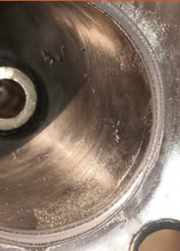
I wouldn’t be satisfied with that bit around four o’clock.
That's what i needed, another set of eyes on it.
non quod, sed quomodo
-
JackyJoll
- Posts: 4442
- Joined: Sun May 03, 2020 10:11 pm
- Has thanked: 245 times
- Been thanked: 1228 times
- Contact:
Re: The JAPton Rebuilders Manual!
P E Irving recommended a minimum 1/32” inlet valve seat width, although that’s for competition.
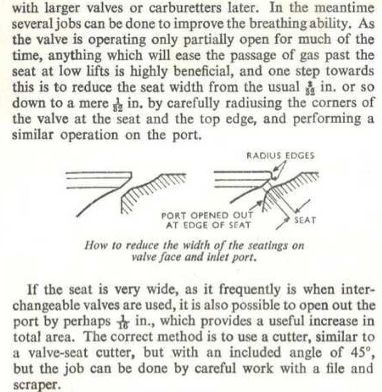
Are you familiar with three-angle valve seat cutting, to avoid making the radial flow change direction more than 15 degrees at a time, when the valve is open by a small amount?
Are you familiar with three-angle valve seat cutting, to avoid making the radial flow change direction more than 15 degrees at a time, when the valve is open by a small amount?