JAPton blog

Discussions and updates on your new bike, your new build, your wishes, wants and desires
User avatar
Rockburner
Posts: 5989
Joined: Sun Mar 15, 2020 11:06 am
Location: Hiding in your blind spot
Has thanked: 10901 times
Been thanked: 3950 times

Re: JAPton blog

Post by Rockburner »

ogri wrote: Sun Apr 12, 2026 5:54 pm Saw a nice Japton on portsdown hill this morning, looked and sounded good.
I bet it was a pre-war v-twin?

I've seen a few of them on Facebook, but i can't remember seeing one using a speedway single like mine.
non quod, sed quomodo
User avatar
ogri
Posts: 598
Joined: Mon Mar 16, 2020 4:11 pm
Location: Wymering
Has thanked: 1266 times
Been thanked: 337 times

Re: JAPton blog

Post by ogri »

No idea about age, looked like a vintage single though.
Fek fascist trump, reform and gbnews!
User avatar
Rockburner
Posts: 5989
Joined: Sun Mar 15, 2020 11:06 am
Location: Hiding in your blind spot
Has thanked: 10901 times
Been thanked: 3950 times

Re: JAPton blog

Post by Rockburner »

Bit of a delay there... sorry about that. Normal service will hopefully be resumed soon.....
(3 weeks of delay due to another project, and since then I've had health issues: currently working around a trapped nerve in my neck which is doing weird things to my left arm and hand).

However - I manage to struggle through a bit of workshop tinkering yesterday, after fixing the Flymo again (the choke butterfly had fallen off the pin, luckily the screw fell into the airbox instead of being ingested!)

I was trying to get the valve timing set correctly.
After a bit of pissing about and accidentally completely fucking up the cam-wheel positioning while looking at the timing pinion I decided to be a bit more systematic about things.

Firstly I identified each keyway on the timing pinion
Image
If you look closely at that photo, you'll see that what I id'd as "2", had a couple of punch-pin marks over it. However, when I took the bike apart, it was set at position "1", so I can only assume that the pin punches marks were from a previous owner/build.

Just another photo of the camwheel.
Image

The timing wheel again
Image

The dial guages over the valves.
Image

After MUCH tinkering:
- set timing pinion on key
- fit case
- tighten nut
- rotate and check valve-opening times
- repeat rotation
- remove nut
- carefully remove case to prevent cam-wheel jumping ship
and repeat....

I ended up with this information :
Image

Moving the Camwheel one tooth forward or backward compared to the timing pinion gives an adjustment of approximately 17degrees, which I did on the 3rd and 5th keyways after seeing that the initial reading was quite a long way out. (Hence 2 sets of readings for those keyways)

Compared to the desired timings:
Image

It looks like actually - position 5 gives the closest to the aggregated correct opening positions. : Exhaust somewhere between 70 and 65 before BDC, and inlet somewhere between 45 and 44 before TDC.

Once I'd found that "sweet spot".... I marked it!!
Image

I then wanted to get the nut done up tight on the timing pinion, but was struggling to hold the crank while I did so.
So, I went furtling in the draw of odd tools.... and dug up this:
Image

One of Dad's home-made contraptions. an old primary drive chain cog with a bit of tube bolted loosely to it. It's far less usable than it looks....

So, I set about improving it.
I figured it would work a lot better if the rod were fastened properly across the cog in 2 places, so set about drilling a new hole in the cog 180 degrees across from the original.

Explain this....
Image


Making progress:
Image

I went through a few of the smaller drills simple because the case-hardened cog was tough to get through with a cheap wood pillar drill!

Eventually I got to the point of drilling the second hole in the pipe - which went relatively smoothly.

Found some bolts (M6 coarse, from the box of metric oddments), and had a lot of fun (not) searching for a pair of nuts (I spent about 2 hours in all during the day furtling through the selection of metric nuts for different jobs).

The tool fitted - but the output shaft itself sticks out from the splines, so I needed to remove some material from the pipe where it crosses the cog.

I initially started drilling again, until the inevitable happened:
Image

So I thought fuck it.
Image

I don't like angle-grinders, but they are good for making a mess.

The finalised tool in situ:
Image

Engagement of the splines is approx 90% - that's good enough for government work.
Image

And the Timing pinion is TIGHT.
It's actually a left-hand thread as well, so theoretically, as long as the engine is "pushing", it should be doing itself up... :D
Image


Next things are to re-adjust the valve clearances back to 0.002" and fully finish the timing chest fit-out.
I think I left out a spacer on the cam-follower shaft, they're moving about too much and "clicking" as the crank rotates - I think it's just the missing spacer (friggin well hope so!), then properly fit the Timing case cover with it's gasket. I need to re-read my notes just to check the assembly.

I've decided to live with the slightly non-perfect push rods for now, but keep looking for replacements. They're relatively easy to replace and will just need the rocker-adjustments redoing to reset the clearances when replaced, ie it shouldn't affect the timing (I believe).

I'll probably also fit the other outer covers that need gaskets next, just so they're done, before mounting the Mag and setting the ignition timing.
non quod, sed quomodo
User avatar
Rockburner
Posts: 5989
Joined: Sun Mar 15, 2020 11:06 am
Location: Hiding in your blind spot
Has thanked: 10901 times
Been thanked: 3950 times

Re: JAPton blog

Post by Rockburner »

Decided to do today's write up while it's all still fresh.
Lots done today.

Priority was finishing off the Timing chest, so the first thing was a dry-assembly of the Timing chest including all the bits and the gasket;
Image

Which seemed to be going well, until I spun the engine over and realised there was as distinct "click-clak" noise coming from "somewhere"...

ffs.


thankfully it wasn't coming from the crankcase....


Primary suspect is the new inlet cam follower possibly clashing against something.


Here's a comparison of the old and new cam followers:
Image

Not much of a difference visible there.. however:
The new one, left is significantly thicker than the old one....
Image

There's also a touch more meat around the pin that holds the metal wheel.
Image


So I tried the old cam follower (which is very, very tired)
Image

I'm still getting the click-clak noises... they're just a touch quieter...

I also reassembled the cam followers with the extra spacer shim at the inboard end of the spindle they sit on, and weirdly I think it's helped a little.

I "think" the new follower IS clashing with the boss cast into the cases that supports the camwheel. But I think putting the shim at the end is moving it enough to clear the boss, and (weirdly) actually putting the follower more central on the cam "path".

We'll see - I need to play with it some more. I had a nice chat with the Guru, who was quite puzzled although he has had a similar experience in the past (at least it's not just me!)

We chatted about a few other things including the push rods and stuff.

Then I got on with the other thing on my mind: the Concentric carb.

I split it down for a clean:
Image

BZZZZZZZZZZZZZZZZZZZZZZZZZZZZZZZZZZZZZZZZZZZZZZZZZT
Image


While that was threatening the fuses I fitted the two lower casing covers.
This is the oil "outlet" fitting being prepped.
The Threebond is a nightmare, the tube has now got several holes in, and it's still runny as hell.
Image


Messy
Image

In the end I just poured the Threebond onto the newspaper and spread it thinkly with my finger!
Image


Next, I pulled down an old G-clamp I'd liberated from Dad's workshop, I want it for a specific job and it needs some modifying...
Image


THIS is what I want the clamp for:
Image

To fit the push-rod tubes you have to hoik the push rods out from under the rocker arms, but there's not enough clearance, even with the adjuster wound right off.
With the clamp I can pull the arm up against the valve spring resistance and pull out the push rods. :D

So, happy with that.

I then progressed to the carb again.

Murky waters....
Image

I messed around for a while fitting the carb top to the control cables: the springs on it are seriously strong, and this nerve issue I currently have has weakened my left hand enough to make things like that problematic. (I'm actually having trouble typing this...)

It's a good thing I had a cathartic session of ordering bits yesterday....
Image

Chrome is for trailer-queens. :D :obscene-birdiedoublered:

I bet the guy sold the carb because he couldn't get it to stop leaking.... Oh well - no matter, new Premier style float-chamber is en route already, along with a few more AMAL goodies. :D


So - next session will be trying to get to the bottom of the click-clak!
non quod, sed quomodo
User avatar
Rockburner
Posts: 5989
Joined: Sun Mar 15, 2020 11:06 am
Location: Hiding in your blind spot
Has thanked: 10901 times
Been thanked: 3950 times

Re: JAPton blog

Post by Rockburner »

The Amal parts arrived today, so I snuck out into the workshop again! :D

Gaskets, float bowl, stainless allen screws, stay-up kit, and a nice mesh "trumpet"
Image

So I started assembling the thing.

The "stay-up" kit is mostly material changes: the float is a military spec material that won't sink, and the mounting tangs are steel (the original part is entirely plastic), so you can easily adjust the float height just by tweaking the tang (phnar!). The float needle is Viton tipped.
Image

I was also going through all my Amal stuff, tidying it up and separating it out into relevant groups. I decided to pack up all the Monobloc stuff into a box to be put into store. I also had a load of random jets and needles from other carb types, so I put those safely away too.
Image

The banjo from the Concentric was a tap rusty, so it got a good brassing.
Image


The single feed fitting from the Monobloc fits the Concentric just fine, so I didn't need to buy another.
Image


I have quite a few main jets.....
Image

230 - 310, and a couple of outliers (140, 360). I've decided to start with a 260 in the Concentric so I can then work up or down.


Mostly there:
Image

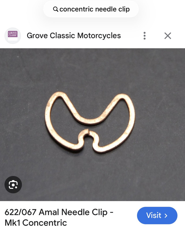
Unfortunately it turns out the sodding needle clip is knackered - it's actually broken across the important bit, so I need to order a new one.
You can "just" make out the break.
Image


So I then turned back to the investigation of the timing chest.

First I dropped the push rods out.
Image

The idea being that I can see if the noise happens without any interference from the valve springs.
Like this I can hold the rod in place to provide "some" resistance.
Image


Being a numpty, I accidentally undid that blanking bolt in the timing chest cover, DAGNABBIT!
Image

Bloomin' thing.
Image

So - to make it a little more secure, I added a springwasher
Image

My investigations were pretty low in results tbh, I still can't quite figure it out, but the old exhaust side cam follower IS a little loose on the spindle, and the roller wheel IS a little loose on it's bushing.... so I may just have to bite the bullet and get another one. Whether that slackness is enought to cause the clicking noise, I'm not sure, but its certainly a slackness that shouldn't be there. It could be that with the valve spring resistance, it's causing movement of the cam follower that is making the clack noises.

There was a concern that the spindle itself might be worn, but the new cam follower seems solid on the spindle, so I think that's ok.

I also took some measurements of the push rods so I can look into buying some stainless tubeing to make new ones.
Image[/url]IMG_20260529_191941_407 by James Bridge-Butler, on Flickr

Image

I think 1/32" wall thickness (info supplied from the Guru, who had a pair without caps fitted) is a mite thin, so I may try to get slightly thicker tubing if available.

The push rod ends are soldered on, so that's going to be a fun job swapping them over... yet more opportunity for conflagations!

Next time I try the timing chest I'm going to dribble some oil onto the cam follower spindle and the rest of the area, it could be that a layer of R is all it needs?
non quod, sed quomodo
JackyJoll
Posts: 4435
Joined: Sun May 03, 2020 10:11 pm
Has thanked: 245 times
Been thanked: 1225 times
Contact:

Re: JAPton blog

Post by JackyJoll »

Rockburner wrote: Fri May 29, 2026 9:01 pm
Unfortunately it turns out the sodding needle clip is knackered - it's actually broken across the important bit, so I need to order a new one.
You can "just" make out the break.
Image
iansoady
Posts: 501
Joined: Thu Mar 19, 2020 10:12 am
Has thanked: 72 times
Been thanked: 242 times

Re: JAPton blog

Post by iansoady »

They often do that. I've probably got a couple lying about but you're probably better getting one from Hitchcocks or Burlen.
User avatar
Rockburner
Posts: 5989
Joined: Sun Mar 15, 2020 11:06 am
Location: Hiding in your blind spot
Has thanked: 10901 times
Been thanked: 3950 times

Re: JAPton blog

Post by Rockburner »

JackyJoll wrote: Sat May 30, 2026 12:28 pm
Rockburner wrote: Fri May 29, 2026 9:01 pm
Unfortunately it turns out the sodding needle clip is knackered - it's actually broken across the important bit, so I need to order a new one.
You can "just" make out the break.
Image
Genuine Manx!
:D
non quod, sed quomodo
User avatar
Rockburner
Posts: 5989
Joined: Sun Mar 15, 2020 11:06 am
Location: Hiding in your blind spot
Has thanked: 10901 times
Been thanked: 3950 times

Re: JAPton blog

Post by Rockburner »

oooo - interesting little bit of information....
The split in the clip is part of the design.
From here.
https://amalcarb.co.uk/technical/rebuil ... arburetter

ok - so I'll have another go at getting it in (may still end up needing a new one though)
non quod, sed quomodo
User avatar
Rockburner
Posts: 5989
Joined: Sun Mar 15, 2020 11:06 am
Location: Hiding in your blind spot
Has thanked: 10901 times
Been thanked: 3950 times

Re: JAPton blog

Post by Rockburner »

When was I last here... sheesh.... I need to pull my finger out.


So: I bought myself a new cam-follower.
Image

And today I tried it out to see if it made any difference to that annoying "clickety-clack" noise I'm getting.

It didn't. (ffs)

However the follower DOES sit on the spindle MUCH tighter, so I'm going to use it. It also seems to fit nicely when the cover is on, ie the float of the cam-followers along the spindle is well within the desired tolerance (ie there's a tad of movement :D), so I'm happy to use it. Next job with that is to try assembly "wet", with some oil dribbled onto it.

I also want to file a notch into the lug of it - I noticed that one of the old followers has such a notch (see below), and what it does is allow oil to get onto the spindle. There's no direct oil feed, the oiling is done by "splash". Having said that - the cam-follower-spindle actually has a channel cut into the top of it, which I can only assume is an oil "trap" to keep the spindle lubricated. Cutting a notch into the cam-follower-spindle lug will allow the oil that is splashed about to get into that channel, and from there it would lubricate the cam-followers on the spindle. So - I kinda wonder why the followers don't have that notch as they come, but it is easily something that could be missed when making up a pattern part, especially as it could well be that (like my engine) only 1 of the followers in the engine the pattern maker had, had a notch.
Image

Job for the next visit anyway, because while I was pondering the clickety-clack, I decided to have a go at refurbing/remaking the push rods.

First I took some highly accurate measurements, to ensure that I had the original lengths of the two push rods BEFORE I took the caps off.
Image
(ahem :D).

Image

I decided to try "safe" heat first to remove the caps, I wasn't sure exactly how they were secured, the normal method is soldering, but the Guru told me that it's also perfectly valid to use epoxy, so these could be either.
Image

This one was epoxied!
Image

The other end was soldered! go figure!
Image

Re-usable push-rod caps, steel.
Image

Did my best to give everything a good clean up
Image

New pipe on left... old on right.
These new ones should be a tad stronger by the looks of it!!Image

The new pipe came a tad long, 12", but that's cool
Image

Precision marking for cutting (ahem)
Image

And some hack-saw action
Image

More high precision measurements.... :D
Image

Close enough for government work?
Image

I always like to dress a hole nicely.... (ahem)
Image

Using Meths to clean up the dust and dirt
Image

The original plan WAS to try to solder the caps onto the push rods, I promise you. However... I never been good at soldering, but I did give it a try with a propane can (and yes, I DID burn my fucking finger tips, again), unsuccessfully... so err...

i cheated.
Image

Trigger clamps for the win.
Image

The second one was a bit of a bugger, for some odd reason the upper cap (the "cupped" one) refused to go onto the rod easily, no matter how much I cleaned up the pipe, or scrapped out the fitting on the cap. In the end I just gave it a bit of a bash... :D
Image


They're roughly the same length, visually anyway.

To be fair, the "exact" length isn't terribly important, as long they fit between the cam-follower and the rocker arm within the range of movement of the adjuster on the rocker arm - there's at least 1/4" of play in there..... :D And now I know how to do the job, I can disassemble them, file a bit more off the ends and re-glue them if they're too long. :D

While I was in the workshop I figured I'd also swap the oil feed fittings which I bought replacements for. :)

First I pulled the old, utterly knackered fittings off: using my "new" flare spanner found and bought specifically for this job! :D
Image

Shiny new fittings installed!
Image

I gave the feed tubes a clean while I was here. They feed an oil dribble from the rocker box to the valve stem.
Image

Fitted the dribble-tubes.
Image

These are the old fittings for the dribble tubes, they're utterly shot.
Image

As is the main inlet feed fitting, new one behind it with the oil feed banjo being tested.
Image

Image

A couple of these should fit..... (despite being metric!)
Image

But.... and here's the rub.... the sodding main thread is wrong.
Image

They're both 3/8" diameter thread, but the OLD one is 26tpi (and so BSC), the new one is 28 tpi... and I can't for the live of me figure out what that is supposed to be. It's not BSF, it's not BSW, it's not UNC and it's not metric (I don't think ? ). So I may well be phoning the supplier tomorrow to find out just what tf it is!

Tune in next time for some lubed up action! :D

non quod, sed quomodo
User avatar
Rockburner
Posts: 5989
Joined: Sun Mar 15, 2020 11:06 am
Location: Hiding in your blind spot
Has thanked: 10901 times
Been thanked: 3950 times

Re: JAPton blog

Post by Rockburner »

Interesting conversation with the Guru this afternoon....

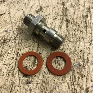
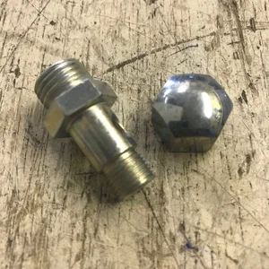
I hadn't realised it, but that banjo "post" fitting has a counterpart in the Pilgrim pump outlet, which is BSP as standard, and the Rocker box fitting is BSC as standard.

Here's photos of the 2 parts from the supplier...

Image

Image

Apart from the machined channel on the upper part.... they're both nigh on identical banjo fittings. It's quite within the bounds of probablity that the BSP pump outlet part (the lower photo) has been modernised to have the channel cut into it to improve oil flow and that photo is of an older style part, so the parts would look virtually identical when you're just picking them up and throwing them into a package.

So it's quite likely I've just been sent the wrong part... hey ho, I can easily see a mistake like that happening, we'll see what they say at the suppliers....
non quod, sed quomodo
User avatar
Ian
Posts: 724
Joined: Tue Jul 18, 2023 9:25 am
Has thanked: 1351 times
Been thanked: 575 times

Re: JAPton blog

Post by Ian »

Some banjos have a recess to work with the bottom one.
If the inside of your banjo is straight you need the top one
Post Reply