Page 7 of 9
Re: 1972 Kawasaki 500 H1B
Posted: Mon Jul 14, 2025 2:06 pm
by Mr. Dazzle
Yeah that's right, the two small wires go in/out of the primary side of the coil and the HT lead grounds the secondary side. The little LT wires 'charge up' the primary side to make a magnetic field, then when the LT circuit is cut that field collapses rapidly and induces a very high (but short lived) voltage in the secondary coil, which is attached to the spark plug, which is grounded by the cylinder head.
If you're convinced the coil, lead and plug are good then then only thing really left is the LT supply side.
Well that's not quite true, because the aforementioned electronic ignition could still be on the fritz. I'm guessing there's no mechanical distributor any more and it has a separate set of solid state parts for each LT circuit? That's another reason to see if moving the LT feeds about changes which sparker has the problem. You could also try changing the LT feeds at the ignition end, which would maybe tell you whether it's a problem with the wires or with the 'tronics.
Re: 1972 Kawasaki 500 H1B
Posted: Mon Jul 14, 2025 2:48 pm
by Taipan
Is the ignition system (easily?) interchangeable with your other bike?
Re: 1972 Kawasaki 500 H1B
Posted: Mon Jul 14, 2025 2:48 pm
by Skub
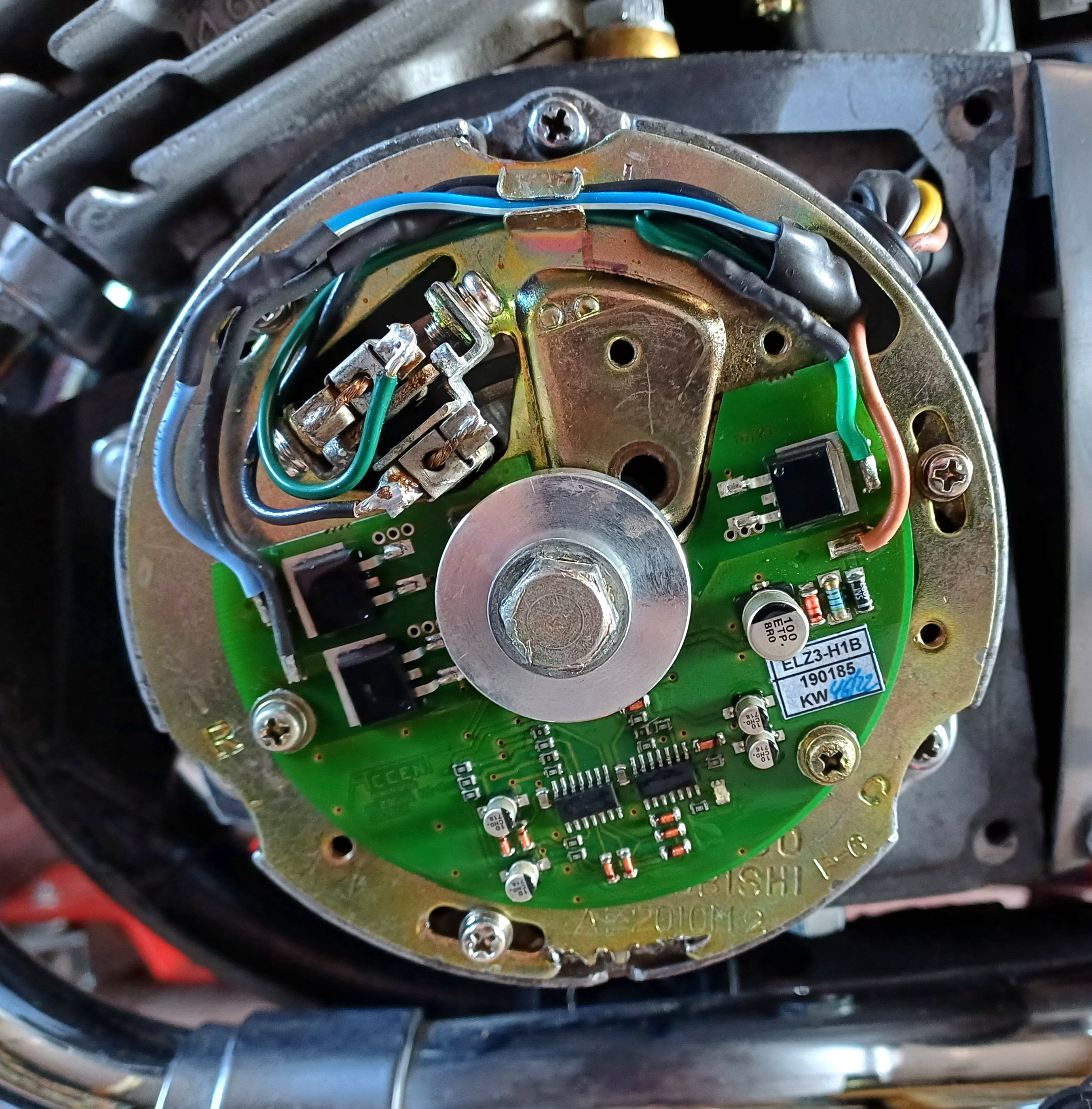
Yeah,the Accent seems to have separate parts for each of the three pots,giving what little I know of a pcb!
- 20250714_143609.jpg (1.99 MiB) Viewed 211 times
Re: 1972 Kawasaki 500 H1B
Posted: Mon Jul 14, 2025 2:49 pm
by Skub
Taipan wrote: Mon Jul 14, 2025 2:48 pm
Is the ignition system (easily?) interchangeable with your other bike?
Different animals TP. The A is CDI,the Accent is made for low voltage points systems.
Re: 1972 Kawasaki 500 H1B
Posted: Mon Jul 14, 2025 3:01 pm
by Yorick
Skub wrote: Mon Jul 14, 2025 1:52 pm
Mr. Dazzle wrote: Mon Jul 14, 2025 1:31 pm
Did you connect everything back up properly on the LT side of the coil when you replaced it? Or maybe disturbed something else in the process.
Could you also try switching the LT supply between different coils so the "wrong" plugs fire? I'm just scratching my head trying to picture the sparking sequence of a 2T triple

On the Bonnie it's dead simple, both plugs fire every time it's at TDC (give or take some advance).
Obviously don't do this when trying to actually start it.
Just thinking that if you move the LT connections and move your problem, there's your issue.
I was pretty careful with the connectors and I'd be happy they are all sound. There's only two wires for each coil. Switching the feed to see if the problem moves I should have done,but haven't yet. Convinced by the strobe,probably.
Firing order is 1 2 3 as you sit on the bike.
120 throw gives almost perfect balance. I remember putting a 50p piece on the fuel cap of my kettle. Didn't move when I revved it

Re: 1972 Kawasaki 500 H1B
Posted: Mon Jul 14, 2025 3:08 pm
by Yorick
- Screenshot_20250714_150407_Samsung Internet.jpg (399.92 KiB) Viewed 452 times
Re: 1972 Kawasaki 500 H1B
Posted: Mon Jul 14, 2025 3:20 pm
by Mr. Dazzle
Skub wrote: Mon Jul 14, 2025 2:48 pm
Yeah,the Accent seems to have separate parts for each of the three pots,giving what little I know of a pcb!

Yeah each of those large black 'chips' is a switch by the looks of it. I.e. a transistor, they'll turn on/off to fire teh plugs. One of them could be malfunctioning - or the wires to/from it could be. Could also be one of them has a poor earth.
Annoying things, electronics

Re: 1972 Kawasaki 500 H1B
Posted: Mon Jul 14, 2025 3:35 pm
by Mr. Dazzle
BTW, I'm guessing the coils have blue, green and black wires???
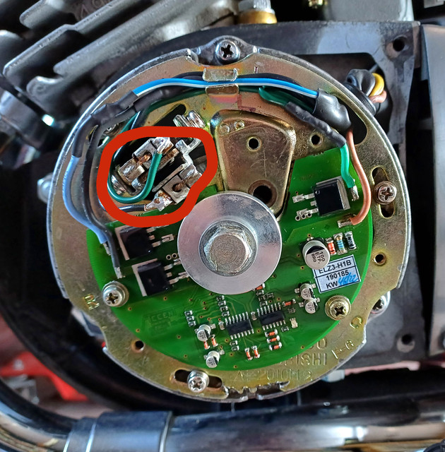
Just looking at it, seems like the brown wire is common and the blue, green and black wires each relate to one plug. Some of the soldering on the thing at about 10 o'clock doesn't look too clever.
But yeah, I'd be tempted to move the LT connections about and see if the problem shifts. Looking at that photo I can't tell if it's possible to also unplug the LT wires at this ^^^ end to try the same thing.
Re: 1972 Kawasaki 500 H1B
Posted: Mon Jul 14, 2025 3:44 pm
by KungFooBob
For £500 plus expenses....
Re: 1972 Kawasaki 500 H1B
Posted: Mon Jul 14, 2025 4:56 pm
by Skub
KungFooBob wrote: Mon Jul 14, 2025 3:44 pm
For £500 plus expenses....
PM me your number just in case I'm tempted.
Re: 1972 Kawasaki 500 H1B
Posted: Mon Jul 14, 2025 5:08 pm
by Skub
Mr. Dazzle wrote: Mon Jul 14, 2025 3:35 pm
BTW, I'm guessing the coils have blue, green and black wires???
Just looking at it, seems like the brown wire is common and the blue, green and black wires each relate to one plug. Some of the soldering on the thing at about 10 o'clock doesn't look too clever.
But yeah, I'd be tempted to move the LT connections about and see if the problem shifts. Looking at that photo I can't tell if it's possible to also unplug the LT wires at this ^^^ end to try the same thing.
The 10 o'clock soldering is the stator brushes,hard to make them look tidy,even new they are a bit gash. I'll rule out the stator/battery voltage when I test ride it under load. The LT connections at the pcb end are soldered and with my soldering skills I might try that if I was prepared to throw it in the bin!

Re: 1972 Kawasaki 500 H1B
Posted: Mon Jul 14, 2025 7:35 pm
by Skub
Yorick wrote: Mon Jul 14, 2025 3:08 pm
Screenshot_20250714_150407_Samsung Internet.jpg
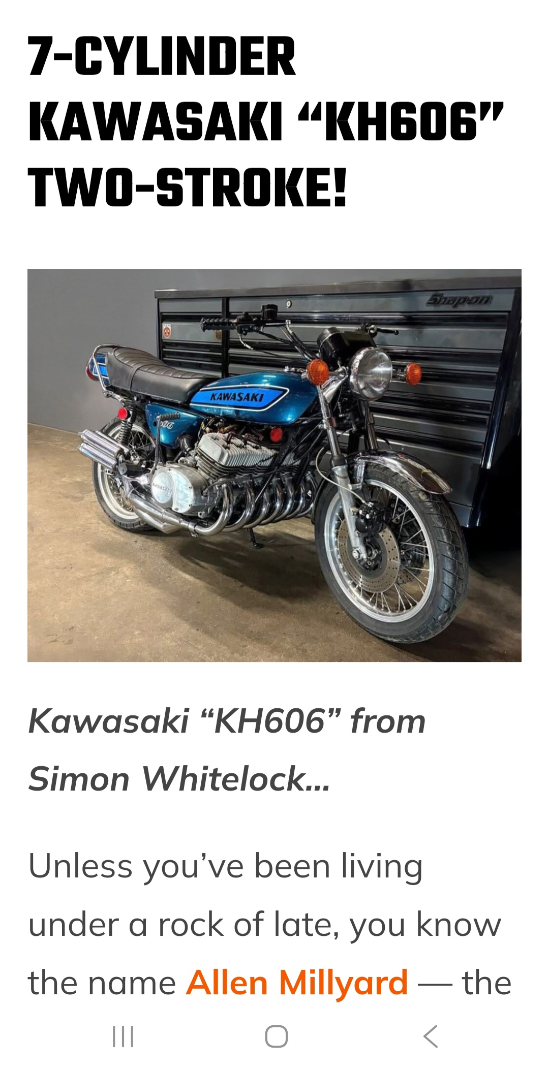
I've spoken to Simon Whitelock on the UK triples f/b group,a nice fella. I'm currently picking his brains.

Re: 1972 Kawasaki 500 H1B
Posted: Mon Jul 14, 2025 9:56 pm
by Skub
Last job for tonight.
I swapped the left coil with the centre coil and this resulted in a good spark jump on the centre. Using the feed from the centre coil to the left gave no spark.
Likely then it's either a fault in the loom,or the Accent? The black wire and the brown wire from the centre coil feed to the Accent pcb have good continuity,but I don't know if that proves much.
I'm betting on the Accent.
Pickups to Outputs are all on that one PCB.
Re: 1972 Kawasaki 500 H1B
Posted: Tue Jul 15, 2025 6:51 am
by Eclipse
Skub wrote: Mon Jul 14, 2025 2:48 pm
Yeah,the Accent seems to have separate parts for each of the three pots,giving what little I know of a pcb!
Behind that large aluminium "spacer" there should be 3 small black hall effect sensors mounted on the pcb equally spaced around the centre hole.
One of those will be for the centre cylinder, might be worth checking that out to see if you can find anything untoward.
There are lots of videos online about how to check them but basically you connect a VM to the legs of it and when the magnet goes past it
you should see a voltage spike.
Re: 1972 Kawasaki 500 H1B
Posted: Tue Jul 15, 2025 7:58 am
by Mr. Dazzle
Do the LT wires have plugs at both ends? I.e. cab you swap them about so you can try each wire in turn with the same plug/coil/cylinder combo. That'd tell you if it's the accent or the wires right?
I'd still be tempted to give the accent it's own dedicated power/earth lines straight to the battery too, even if only temporarily. I haven't forgotten about the involvement of the indicators...
Re: 1972 Kawasaki 500 H1B
Posted: Tue Jul 15, 2025 8:13 am
by KungFooBob
Convert it back to points
Re: 1972 Kawasaki 500 H1B
Posted: Tue Jul 15, 2025 11:31 am
by Skub
KungFooBob wrote: Tue Jul 15, 2025 8:13 am
Convert it back to points
I did consider that option. You can get it all NOS,but it'd come in around the same price as a new Accent....
Re: 1972 Kawasaki 500 H1B
Posted: Tue Jul 15, 2025 12:06 pm
by Yorick
Can't you take all the bits from the other one to test?
Re: 1972 Kawasaki 500 H1B
Posted: Tue Jul 15, 2025 12:27 pm
by Skub
Skub wrote: Mon Jul 14, 2025 2:49 pm
Taipan wrote: Mon Jul 14, 2025 2:48 pm
Is the ignition system (easily?) interchangeable with your other bike?
Different animals TP. The A is CDI,the Accent is made for low voltage points systems.
Yorick wrote: Tue Jul 15, 2025 12:06 pm
Can't you take all the bits from the other one to test?
Re: 1972 Kawasaki 500 H1B
Posted: Tue Jul 15, 2025 2:02 pm
by Taipan
Those two connectors look messy and like someone's played around with them before? I cant see them too clearly, but could have a dry joint there? You can stick a soldering iron on soldered joints until they suddenly shine (solder reaches melt point) and that cures a lot of dry joints. We often used to turn PCBs upside down and
shine all the joints on the underside when encountering a board fault.